Product Description
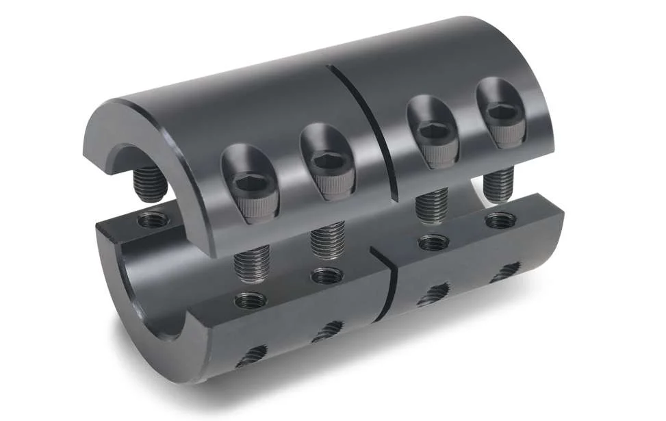
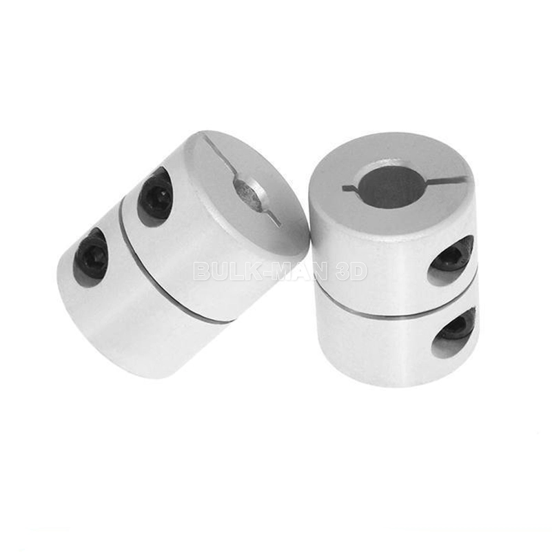
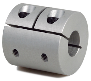
GR-32×42 GR Motor Shaft Coupling Rigid Coupling
Description of GR-32×42 GR Motor Shaft Coupling Rigid Coupling
>The material is aluminum alloy, and the middle bellows is made of stainless steel with excellent corrosion resistance
>Laser welding is used between bellows and shaft sleeve, with zero rotation clearance, suitable for CHINAMFG and reverse rotation
>Bellows structure can effectively compensate radial, angular and axial deviation
>Designed for servo motor stepper motor
>Fastening method of setscrew
Catalogue of GR-32×42 GR Motor Shaft Coupling Rigid Coupling
|
model parameter |
common bore diameter d1,d2 |
ΦD |
L |
LI |
L2 |
L3 |
N |
F |
tightening screw torque |
|
GR-16×27 |
4,5,6,6.35,7,8 |
16 |
27 |
7.5 |
2 |
8 |
13.5 |
3 |
0.7 |
|
GR-20×32 |
5,6,6.35,7,8,9,9.525,10,11,12 |
20 |
32 |
7.2 |
2.8 |
12 |
18 |
3.5 |
0.7 |
|
GR-22.5×34 |
5,6,6.35,7,8,9,9.525,10,11,12 |
22.5 |
34 |
8.05 |
2.8 |
12.3 |
20.2 |
4.5 |
1.7 |
|
GR-25×37 |
6,6.35,7,8,9,9.525,10,11,12 |
25 |
37 |
9.5 |
3 |
12 |
20.2 |
4.5 |
1.7 |
|
GR-32×42 |
8,9,10,11,12,12.7,14,15 |
32 |
42 |
8 |
4 |
18 |
27.2 |
5.5 |
4 |
|
GR-40×51 |
8,9,9.525,10,11,12,12.7,14,15,16,17,18,19,20 |
40 |
51 |
9.5 |
6 |
20 |
34.5 |
5.5 |
4 |
|
GR-55×57 |
10,11,12,12.7,14,15,16,17,18,19,20,22,24,25 |
55 |
57 |
9 |
6 |
27 |
51.9 |
6.25 |
7 |
|
GR-65×81 |
10,11,12,12.7,14,15,16,17,18,19,20,22,24,25,28,30,32,35,38 |
65 |
81 |
19.5 |
7 |
28 |
60.5 |
8.9 |
7 |
|
model parameter |
Rated torque(N.m) |
allowable eccentricity (mm) |
allowable deflection angle (°) |
allowable axial deviation (mm) |
maximum speed (rpm) |
static torsional stiffness (N.M/rad) |
weight (g) |
|
GR-16×27 |
0.8 |
0.1 |
2 |
-0.8 |
20000 |
150 |
8 |
|
GR-20×32 |
1.5 |
0.1 |
2 |
-1.2 |
18000 |
220 |
13 |
|
GR-22.5×34 |
1.8 |
0.15 |
2 |
-1.2 |
16000 |
300 |
22 |
|
GR-25×37 |
2 |
0.15 |
2 |
-1.2 |
15000 |
330 |
30 |
|
GR-32×42 |
2.5 |
0.2 |
2 |
-1.7 |
11000 |
490 |
53 |
|
GR-40×51 |
6.4 |
0.3 |
2 |
-1.7 |
10000 |
530 |
85 |
|
GR-55×57 |
12 |
0.3 |
2 |
-1.7 |
9000 |
860 |
170 |
|
GR-65×81 |
18 |
0.2 |
2 |
-1.8 |
4500 |
900 |
280 |
/* January 22, 2571 19:08:37 */!function(){function s(e,r){var a,o={};try{e&&e.split(“,”).forEach(function(e,t){e&&(a=e.match(/(.*?):(.*)$/))&&1

How to Properly Install a Rigid Shaft Coupling for Optimal Performance and Reliability
Proper installation of a rigid shaft coupling is essential to ensure optimal performance and reliability in mechanical systems. Here are the steps to follow for a successful installation:
- Shaft Preparation: Ensure that the shafts to be connected are clean, smooth, and free from any burrs or contaminants that could affect the coupling’s performance.
- Alignment: Align the two shafts accurately to minimize misalignment during installation. The alignment process is critical as any misalignment can lead to premature wear and reduced coupling efficiency.
- Fitment: Choose the appropriate size of the rigid shaft coupling that matches the shaft diameters. Carefully slide the coupling onto one shaft at a time.
- Fastening: For one-piece rigid couplings, ensure that the coupling is fitted snugly onto both shafts. For two-piece couplings, bolt the two halves together securely around the shafts.
- Tightening: Use the recommended torque value and follow the manufacturer’s guidelines to tighten the coupling bolts properly. Over-tightening can cause distortion, while under-tightening can lead to slippage and reduced torque transmission.
- Inspection: After installation, inspect the coupling to ensure that it is centered and aligned correctly. Check for any signs of misalignment or interference during rotation.
- Lubrication: Some rigid couplings may require lubrication at the friction points to reduce wear and friction. Follow the manufacturer’s recommendations for lubrication intervals and types.
- Load Testing: Perform load testing on the system to verify the coupling’s performance and check for any unusual vibrations or noises during operation.
- Regular Maintenance: Include the rigid coupling in your regular maintenance schedule. Periodically check for signs of wear, misalignment, or damage, and replace the coupling if necessary.
By following these installation steps and best practices, you can ensure that the rigid shaft coupling operates optimally, providing reliable torque transmission and contributing to the overall efficiency and longevity of the mechanical system.

What design considerations are crucial when selecting a rigid shaft coupling for a specific application?
Selecting the right rigid shaft coupling for a specific application involves careful consideration of several design factors to ensure optimal performance and reliability. Here are crucial design considerations to keep in mind:
- Torque Transmission: Determine the maximum torque that the coupling needs to transmit. The coupling’s torque rating should match or exceed the application’s requirements to prevent overloading.
- Shaft Size and Type: Choose a coupling that accommodates the shaft sizes and types of the connected equipment. The coupling’s bore sizes should match the shaft diameters for a secure fit.
- Alignment Capability: Consider the alignment accuracy needed for your application. Rigid couplings offer excellent alignment, but some applications might require higher precision than others.
- Space Constraints: Evaluate the available space around the coupling area. Some couplings might have a compact design suitable for tight spaces, while others might require more clearance.
- Environmental Conditions: Assess the operating environment for factors such as temperature, humidity, and presence of corrosive substances. Choose a coupling with appropriate materials and coatings for durability in the given conditions.
- Shaft Misalignment: Determine the potential misalignments the coupling will need to accommodate. While rigid couplings have limited flexibility, they can handle small misalignments. Consider whether angular or axial misalignments are more significant in your application.
- Operating Speed: Evaluate the rotational speed of the machinery. Some couplings have speed limits, and exceeding these limits can lead to vibrations and premature wear.
- Dynamic Loads: Consider any dynamic loads, shocks, or impacts that the coupling might experience during operation. Choose a coupling that can handle these loads without failure.
- Torsional Rigidity: High torsional rigidity ensures efficient torque transmission and minimizes torsional vibrations. Evaluate whether the coupling’s stiffness aligns with your application’s requirements.
- Attachment Method: Determine how the coupling will be attached to the shafts. Different couplings use set screws, clamps, keyways, or other attachment methods. Select a method that suits your application’s needs.
- Cost Considerations: Balance the desired features with your budget. While more advanced couplings might offer additional benefits, they could also be more expensive.
It’s important to collaborate with coupling manufacturers, engineers, or experts to ensure the selected coupling aligns with the specific demands of your application. Coupling suppliers can provide valuable guidance based on their product knowledge and experience with various applications.
By carefully evaluating these design considerations, you can select a rigid shaft coupling that delivers reliable performance, reduces maintenance needs, and contributes to the overall efficiency of your machinery.

Can Rigid Shaft Couplings Handle Misalignment Between Shafts Effectively?
Rigid shaft couplings are not designed to accommodate misalignment between shafts effectively. Unlike flexible couplings, which can bend or flex to some degree to compensate for misalignment, rigid couplings are inflexible and require precise alignment for proper operation.
When using rigid shaft couplings, it is crucial to ensure that the two shafts being connected are aligned with high accuracy. Misalignment between the shafts can lead to various issues, including:
- Vibrations: Misalignment can cause vibrations and increase stress on the coupling and connected machinery, leading to premature wear and reduced performance.
- Increased Stress: Misalignment results in additional stress on the shafts and coupling, which may lead to fatigue failure over time.
- Reduced Efficiency: Misalignment can result in power loss and reduced overall system efficiency.
- Noise: Misalignment may generate noise during operation, leading to potential discomfort for operators and additional wear on components.
To ensure the effective functioning of rigid shaft couplings, it is crucial to align the shafts accurately during installation. The alignment process typically involves using precision tools and techniques to achieve the desired alignment tolerances.
For applications where misalignment is expected or unavoidable, flexible couplings such as beam couplings or jaw couplings may be more suitable as they can accommodate slight misalignments and reduce the transmission of shock and vibration between shafts.
Overall, rigid shaft couplings are best suited for applications where precise shaft alignment is feasible and necessary for optimal performance. Proper alignment and regular maintenance are essential to maximize the life and efficiency of rigid couplings in mechanical systems.


editor by CX 2024-03-27
Leave a Reply