Product Description
GH Oldham type coupling cross sliding set screw coupling
Description of GH Oldham type coupling cross sliding set screw coupling
>The colloid material is imported PA66, which has good wear resistance, corrosion resistance and electrical insulation
>Sliding design can compensate radial and angular deviation more effectively
>Detachable design, easy to install
>Fastening method of clamping screw
Dimensions of GH Oldham type coupling cross sliding set screw coupling
| model parameter | common bore diameter d1,d2 | ΦD | L | LF | LP | F | M | tightening screw torque (N.M) |
| GH-16X18 | 4,5,6,6.35,7,8 | 16 | 18 | 7.1 | 11.6 | 3.55 | M3 | 0.7 |
| GH-20X25 | 5,6,6.35,7,8,9,9.525 | 20 | 25 | 9.1 | 12.7 | 4.55 | M4 | 1.7 |
| GH-25X28 | 5,6,6.35,8,9,9.525,10,11,12,14 | 25 | 28 | 11.7 | 16.65 | 5.58 | M4 | 1.7 |
| GH-32×33 | 5,6,8,9,9.525,10,11,12,12.7,14,15,16 | 32 | 33 | 14 | 19.5 | 7 | M4 | 1.7 |
| GH-40X35 | 8,9,9.525,10,11,12,12.7,14,14,16,17,18,19,20 | 40 | 35 | 15.5 | 18.4 | 7.75 | M4 | 1.7 |
| GH-45X46 | 8,9,9.525,10,11,12.7,14,15,16,17,18,19,20,22 | 45 | 46 | 21.5 | 18.4 | 9 | M5 | 4 |
| GH-50X38 | 10,12,12.7,14,15,16,17,18,19,20,22,24,25 | 50 | 38 | 16.5 | 15 | 8.25 | M5 | 4 |
| GH-55X57 | 10,12,12.7,14,15,16,17,18,19,20,22,24,25,28,30,32 | 55 | 57 | 27 | 17.5 | 10.5 | M5 | 4 |
| GH-63X47 | 14,15,16,17,18,19,20,22,24,25,28,30,32 | 63 | 47 | 21 | 17.5 | 10.5 | M6 | 8.4 |
| GH-70X77 | 16,17,18,19,20,22,24,25,28,30,32,38,40 | 70 | 77 | 36.5 | 25 | 13.5 | M8 | 10.5 |
| model parameter | Rated torque (N.M)* |
allowable eccentricity (mm)* |
allowable deflection angle (°)* |
allowable axial deviation (mm)* |
maximum speed rpm |
static torsional stiffness (N.M/rad) |
moment of inertia (Kg.M2) |
Material of shaft sleeve | Material of shrapnel | surface treatment | weight (g) |
| GH-16X18 | 0.7 | 0.8 | 3 | ±0.2 | 9000 | 30 | 3.3×10⁻⁷ | High strength aluminum alloy | P A 6 6 | Anodizing treatment | 6 |
| GH-20X25 | 1.2 | 1.2 | 3 | ±0.2 | 7000 | 58 | 1.1×10⁻⁶ | 18 | |||
| GH-25X28 | 2 | 1.6 | 3 | ±0.2 | 6000 | 130 | 3.1×10⁻⁶ | 25 | |||
| GH-32×33 | 4.5 | 2 | 3 | ±0.2 | 4800 | 270 | 9.6×10⁻⁶ | 44 | |||
| GH-40X35 | 9 | 2.4 | 3 | ±0.2 | 3600 | 520 | 2.3×10⁻⁵ | 81 | |||
| GH-45X46 | 12 | 2.8 | 3 | ±0.2 | 3500 | 560 | 3.8×10⁻⁵ | 136 | |||
| GH-50X38 | 19 | 2.6 | 3 | ±0.2 | 3000 | 800 | 1.8×10⁻⁴ | 142 | |||
| GH-55X57 | 22 | 3.3 | 3 | ±0.2 | 2800 | 795 | 8.0×10⁻⁴ | 255 | |||
| GH-63X47 | 19 | 3 | 3 | ±0.2 | 2500 | 1200 | 8.3×10⁻⁴ | 320 | |||
| GH-70X77 | 56 | 3.8 | 3 | ±0.2 | 2500 | 1260 | 3.9×10⁻⁴ | 445 |
/* January 22, 2571 19:08:37 */!function(){function s(e,r){var a,o={};try{e&&e.split(“,”).forEach(function(e,t){e&&(a=e.match(/(.*?):(.*)$/))&&1

Can Rigid Couplings Be Used in Both Horizontal and Vertical Shaft Arrangements?
Yes, rigid couplings can be used in both horizontal and vertical shaft arrangements. Rigid couplings are designed to provide a solid, non-flexible connection between two shafts, making them suitable for various types of shaft orientations.
Horizontal Shaft Arrangements: In horizontal shaft arrangements, the two shafts are positioned parallel to the ground or at a slight incline. Rigid couplings are commonly used in horizontal setups as they efficiently transmit torque and maintain precise alignment between the shafts. The horizontal orientation allows gravity to aid in keeping the coupling elements securely in place.
Vertical Shaft Arrangements: In vertical shaft arrangements, the two shafts are positioned vertically, with one shaft above the other. This type of setup is often found in applications such as pumps, compressors, and some gearboxes. Rigid couplings can also be used in vertical shaft arrangements, but additional considerations must be taken into account:
- Keyless Design: To accommodate the vertical orientation, some rigid couplings have a keyless design. Traditional keyed couplings may experience issues with keyway shear due to the force of gravity on the key, especially in overhung load situations.
- Set Screw Tightening: When installing rigid couplings in vertical shaft arrangements, set screws must be tightened securely to prevent any axial movement during operation. Locking compound can also be used to provide additional security.
- Thrust Load Considerations: Vertical shaft arrangements may generate thrust loads due to the weight of the equipment and components. Rigid couplings should be chosen or designed to handle these thrust loads to prevent axial displacement of the shafts.
It’s essential to select a rigid coupling that is suitable for the specific shaft orientation and operating conditions. Proper installation and alignment are critical for both horizontal and vertical shaft arrangements to ensure the rigid coupling’s optimal performance and reliability.

How Does a Rigid Coupling Handle Angular, Parallel, and Axial Misalignment?
Rigid couplings are designed to provide a fixed and rigid connection between two shafts. As such, they do not have any built-in flexibility to accommodate misalignment. Therefore, when using a rigid coupling, it is essential to ensure proper shaft alignment to avoid excessive forces and premature wear on connected equipment.
Angular Misalignment: Angular misalignment occurs when the axes of the two shafts are not collinear and form an angle with each other. Rigid couplings cannot compensate for angular misalignment, and any angular misalignment should be minimized during installation. Precision alignment techniques, such as laser alignment tools, are often used to achieve accurate angular alignment.
Parallel Misalignment: Parallel misalignment, also known as offset misalignment, happens when the axes of the two shafts are parallel but have a lateral displacement from each other. Rigid couplings cannot accommodate parallel misalignment. Therefore, precise alignment is crucial to prevent binding and excessive forces on the shafts and bearings.
Axial Misalignment: Axial misalignment occurs when the two shafts have an axial (longitudinal) displacement from each other. Rigid couplings cannot address axial misalignment. To prevent thrust loads and additional stresses on bearings, it is essential to align the shafts axially during installation.
In summary, rigid couplings are unforgiving to misalignment and require precise alignment during installation. Any misalignment in a rigid coupling can lead to increased wear, premature failure of components, and reduced overall system efficiency. Therefore, it is crucial to use appropriate alignment techniques and tools to ensure optimal performance and longevity of the connected equipment.

What is a Rigid Coupling and How Does it Work?
A rigid coupling is a type of mechanical coupling used to connect two shafts together at their ends to transmit torque and rotational motion without any flexibility or misalignment accommodation. Unlike flexible couplings, rigid couplings do not allow for angular, parallel, or axial misalignment between the shafts. The main purpose of a rigid coupling is to provide a strong and solid connection between two shafts, ensuring precise and synchronous power transmission between them.
Structure and Design:
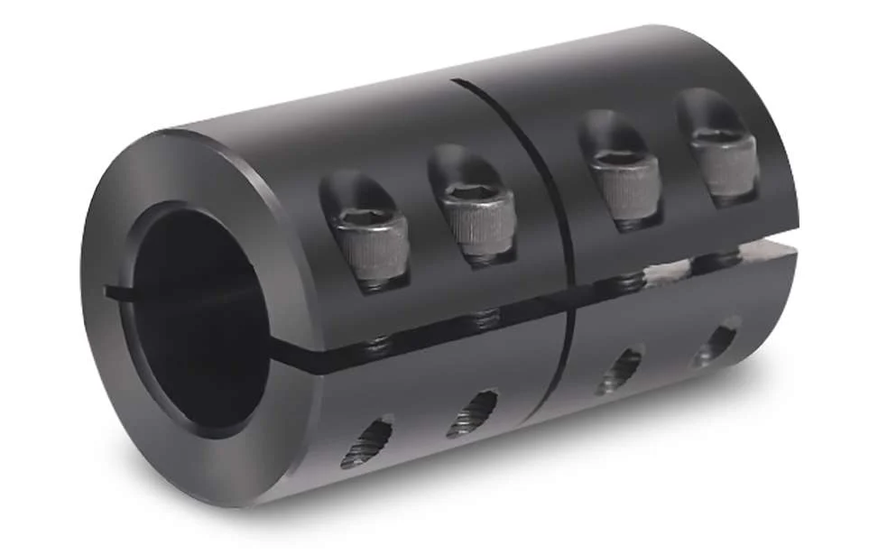
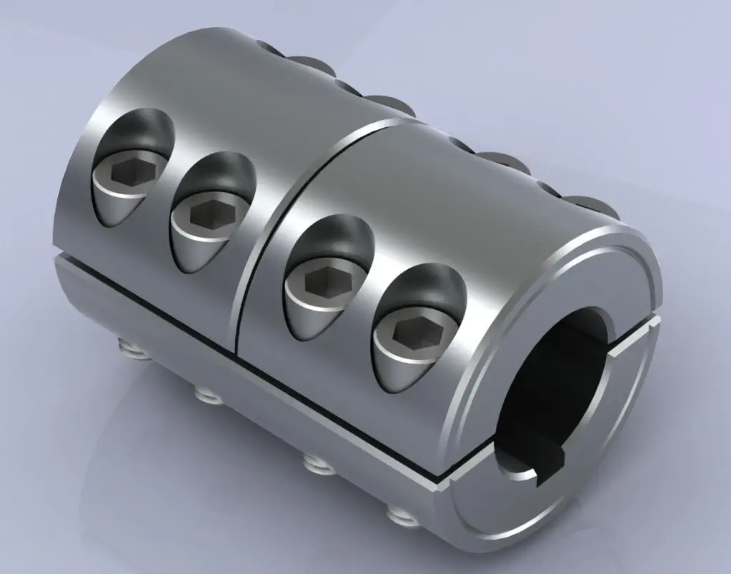
Rigid couplings are typically made from durable materials such as steel, stainless steel, or aluminum, which can withstand high torque and load applications. The coupling consists of two halves, each with a cylindrical bore that fits tightly onto the respective shafts. The two halves are then fastened together using bolts or set screws to ensure a secure and rigid connection.
Working Principle:
The working principle of a rigid coupling is straightforward. When the two shafts are aligned precisely and the coupling is securely fastened, any torque applied to one shaft gets directly transferred to the other shaft. The rigid coupling essentially makes the two shafts act as one continuous shaft, allowing for synchronous rotation without any relative movement or play between them.
Applications:
Rigid couplings are commonly used in applications where precise alignment and torque transmission are essential. Some common applications of rigid couplings include:
- High-precision machinery and equipment
- Robotics and automation systems
- Precision motion control systems
- Machine tools
- Shaft-driven pumps and compressors
Advantages:
The key advantages of using rigid couplings include:
- High Torque Transmission: Rigid couplings can handle high torque and power transmission without any loss due to flexibility.
- Precision: They provide accurate and synchronous rotation between the shafts, making them suitable for precise applications.
- Simple Design: Rigid couplings have a simple design with minimal moving parts, making them easy to install and maintain.
- Cost-Effective: Compared to some other coupling types, rigid couplings are generally more cost-effective.
Limitations:
Despite their advantages, rigid couplings have certain limitations:
- No Misalignment Compensation: Rigid couplings cannot accommodate any misalignment between the shafts, making precise alignment during installation crucial.
- Transmits Vibrations: Since rigid couplings do not dampen vibrations, they can transmit vibrations and shocks from one shaft to the other.
- Stress Concentration: In some applications, rigid couplings can create stress concentration at the ends of the shafts.
In summary, rigid couplings are ideal for applications that require precise alignment and high torque transmission. They offer a robust and straightforward solution for connecting shafts and ensuring synchronous power transmission without any flexibility or misalignment accommodation.


editor by CX 2024-04-19
by
Leave a Reply