Product Description
Type:Coupling, elbow, tee, cross, reducer, cap, mechanical tee, mechanical cross, flange adaptor,etc.
Size:1/2″-12″
Standard:ANSI, ASTM, DIN, JIS, GB, BS, etc.
Material: Ductile Iron ASTM A536, Grade 65–45–12,etc.
Surface finish: passivated, stain polished, mirror polished, e-coating etc.
Usage:
1) Automatic sprinkler system for fire protection on commercial,
civil and municipal constructions like water supplying, gas supplying, heat supplying, etc.
2) Industrial pipeline system on shipping, mine, oil field, textile, powder plant, etc.
3) Pipeline system on subway station, railway station, airport, seaport, bridge, etc.
Advantages:
1. Low price,high quality & fast delivery & strict inspection .
2. The fastest delivery
3. The lowest price
4. Most comprehensive standards and materials for your choice.
5.100% export.
6. Our products EXPORT to Africa, Oceania, mid east, eastern Asia, Western
| Usage |
1) Automatic sprinkler system for fire protection on commercial, civil and municipal constructions like water supplying, gas supplying, heat supplying, etc. 2) Industrial pipeline system on shipping, mine, oil field, textile, powder plant, etc. 3) Pipeline system on subway station, railway station, airport, seaport, bridge, etc. |

Are There Any Safety Considerations When Using Rigid Couplings in Rotating Machinery?
Yes, there are several safety considerations to keep in mind when using rigid couplings in rotating machinery. While rigid couplings offer various advantages, their use in certain applications requires careful attention to safety measures to prevent accidents and equipment damage. Here are some important safety considerations:
– Secure Installation: Proper installation of rigid couplings is crucial to ensure safety. The coupling must be securely mounted and aligned with the shafts to prevent any slippage or disengagement during operation. Use of appropriate mounting hardware, such as high-strength bolts, is essential to maintain the coupling’s integrity under high-speed and high-torque conditions.
– Shaft Alignment: Accurate shaft alignment is necessary to avoid excessive forces and stress on the connected machinery. Misaligned shafts can lead to uneven loading and increased wear on bearings and other components. Regularly inspect and maintain the shaft alignment to prevent premature failures.
– Preventing Over-Torquing: Applying excessive torque during the installation of rigid couplings can lead to equipment damage and compromise safety. Follow the manufacturer’s torque specifications and use torque-limiting tools to prevent over-torquing and potential failures.
– Protective Guards: In some applications, rotating machinery with rigid couplings may pose a safety hazard to personnel working nearby. Install appropriate protective guards and covers to prevent accidental contact with rotating shafts, minimizing the risk of injury.
– Regular Maintenance: Implement a routine maintenance schedule to inspect the rigid couplings and associated equipment. Check for signs of wear, fatigue, or cracks. Address any issues promptly to avoid potential catastrophic failures.
– Operational Speed Limits: Be aware of the operational speed limits specified by the manufacturer for the rigid couplings. Exceeding these limits can result in significant stress and fatigue on the coupling, leading to failure.
– Appropriate Coupling Selection: Choose the appropriate type and size of rigid coupling for the specific application. Using an undersized coupling can lead to excessive loads and potential failure, while an oversized coupling may not efficiently transmit torque.
– Temperature Considerations: Rigid couplings can experience temperature variations during operation. Ensure that the material and design of the coupling are suitable for the anticipated temperature range of the application to maintain safety and performance.
– Training and Awareness: Provide proper training to personnel working with rotating machinery equipped with rigid couplings. Ensure they are aware of safety procedures and potential hazards associated with the equipment.
Adhering to these safety considerations will help ensure the safe and reliable operation of rotating machinery equipped with rigid couplings. Regular maintenance, correct installation, and diligent attention to safety guidelines will minimize risks and contribute to a safe working environment.

What Industries Commonly Use Rigid Couplings for Power Transmission?
Rigid couplings are widely used in various industries for power transmission applications that require a solid and reliable connection between rotating shafts. Some of the industries that commonly utilize rigid couplings include:
- Manufacturing: In the manufacturing industry, rigid couplings are employed in a wide range of equipment, such as conveyors, mixers, pumps, compressors, and machine tools. These couplings ensure precise power transmission and alignment, making them ideal for maintaining accuracy in manufacturing processes.
- Material Handling: Material handling equipment, including cranes, hoists, and elevators, often rely on rigid couplings to transfer power between shafts efficiently. Rigid couplings provide a robust connection that can handle the heavy loads and continuous operation common in material handling applications.
- Automotive: The automotive industry employs rigid couplings in various automotive systems, including drive shafts, transmissions, and steering systems. Rigid couplings contribute to the overall performance and reliability of these components, ensuring smooth power transfer and minimizing vibration.
- Mining and Construction: In the mining and construction industries, rugged and durable power transmission components are crucial. Rigid couplings are used in equipment like crushers, mills, and heavy-duty conveyors, where they can withstand the harsh conditions and heavy loads commonly found in these applications.
- Oil and Gas: The oil and gas industry often utilizes rigid couplings in pumps, compressors, and drilling equipment. Rigid couplings offer consistent and dependable power transmission, which is essential for critical operations in this sector.
- Marine: In marine applications, such as ship propulsion systems and marine pumps, rigid couplings are used to transmit power between the ship’s engine and various equipment. They can handle the dynamic forces and vibrations encountered in marine environments.
- Aerospace: In aerospace applications, where precision and reliability are paramount, rigid couplings play a role in power transmission between various aircraft components.
Rigid couplings are chosen in these industries for their ability to maintain shaft alignment, resist misalignment, and provide a backlash-free connection. Their robust construction and simple design make them suitable for high torque and high-speed applications, where precision and efficiency are crucial.

Materials Used in Manufacturing Rigid Couplings:
Rigid couplings are designed to provide a strong and durable connection between two shafts, and they are commonly made from a variety of materials to suit different applications. The choice of material depends on factors such as the application’s environment, load capacity, and cost considerations. Some common materials used in manufacturing rigid couplings include:
- 1. Steel: Steel is one of the most widely used materials for rigid couplings. It offers excellent strength, durability, and resistance to wear. Steel couplings are suitable for a wide range of applications, including industrial machinery, automotive systems, and power transmission.
- 2. Stainless Steel: Stainless steel couplings are used in applications where corrosion resistance is crucial. They are well-suited for environments with high humidity, moisture, or exposure to chemicals. Stainless steel couplings are commonly used in food processing, pharmaceuticals, marine, and outdoor applications.
- 3. Aluminum: Aluminum couplings are known for their lightweight and corrosion-resistant properties. They are often used in applications where weight reduction is essential, such as aerospace and automotive industries.
- 4. Brass: Brass couplings offer good corrosion resistance and are commonly used in plumbing and water-related applications.
- 5. Cast Iron: Cast iron couplings provide high strength and durability, making them suitable for heavy-duty industrial applications and machinery.
- 6. Bronze: Bronze couplings are known for their excellent wear resistance and are often used in applications involving heavy loads and low speeds.
- 7. Plastics: Some rigid couplings are made from various plastics, such as nylon or Delrin. Plastic couplings are lightweight, non-conductive, and suitable for applications where electrical insulation is required.
It’s essential to consider the specific requirements of the application, including factors like load capacity, operating environment, and cost, when choosing the appropriate material for a rigid coupling. The right material selection ensures that the coupling can withstand the forces and conditions it will encounter, resulting in a reliable and long-lasting connection between the shafts.


editor by CX 2023-08-04
China wholesaler Zs Factory Price High Precision High Gain Type Flexible Couplings for Automation Machinery coupling agent
Product Description
Introduction
- Oldham couplings are a 3 piece design comprised of 2 aluminum hubs press fit CZPT a center disk. Torque transmission is accomplished by mating the slots on the center disk to the drive tenons on the hubs. During operation the center disk slides on the tenons of each hub (which are orientated 90 apart) to transmit torque.
- While the couplings accommodate a small amount of angular and axial misalignment, they are especially useful in applications with parallel misalignment.
- We offers oldham couplings in set screw or clamp styles with bores ranging from 4mm to 35mm. Inch and metric hubs (set screw, clamp style, keyed, or keyless) are interchangeable and can be combined into a single coupling as long as they have the same outside diameter. Oldham coupling hubs are standard in black anodized aluminum for improved lubricity, increased life, and low inertia. Hubs are also available in stainless steel CZPT request for increased corrosion resistance.
Application
- Ideal for many light duty industrial and motion control applications, oldham couplings have the ability to protect more expensive machinery components.
- For example the oldham coupling acts as a torque limiter during overload. When the disk fails, it breaks cleanly and does not allow any transmission of power.
- Oldham couplings also have the advantage of electrical isolation due to the non-conductive nature of the center disk.
- This prevents electrical currents from being passed to delicate instruments which can cause inaccurate data readings or damage.
Feature
- High absorption capacity of radial misaligment
- They do not produce kinematic errors in transmission
- Elimination of loads on shaft
- Mechanical protection against excessive torque
- Replaceable disc
1. We have first-class testing equipment to detect linear guide various data parameters and control the quality of the linear guide.Whenever linear guides must first detected whether the quality is qualified and the unqualified linear guide will be eliminated directly.So we can get the trust of a large customer, and supply them for several years.
2. We have our own R & D capabilities, to help customers solve the problem of non-standard linear guides.We can also according to customer requirements change their own mark.
3. Price, our manufacture ensure that our prices across China are quite competitive.It is better for you to compare prices and quality among suppliers.But everyone knows you can not buy the highest quality products with the lowest price,but our product is the best quailty if you use equal price.
FAQ:
1. When can I get the quotation ?
We usually quote within 24 hours after we get your inquiry. If you are very urgent to get the price,please call us or tell us in your email so that we will regard your inquiry priority.
2. How can I get a sample to check your quality ?
After price confirmed,sample order is available to check our quality.
3. What is your main products ?
Linear motion systems,like lead screws, flexible coupling,Miniature linear guide rails,ball screws,linear rod shaft,ceramic bearings …etc. But also CNC machining centers and CNC machinable tooling boards.
4. Could you get a better price on your products ?
Yes,you can.We will give the best price on all of the products you need,which can help you to compete other companies in your markets.
5. What is the strength of your company ?
We have a engineer team,who have well experienced on product’s and machine designs.We can help you to solve the problems you meet.
Welcome to inquiry US!
| Standard Or Nonstandard: | Standard |
|---|---|
| Shaft Hole: | 10-32 |
| Torque: | 30-50N.M |
| Bore Diameter: | 14mm |
| Structure: | Rigid and Flexible |
| Material: | Aluminum |
| Samples: |
US$ 5/Piece
1 Piece(Min.Order) | |
|---|
| Customization: |
Available
| Customized Request |
|---|

Types of Couplings
A coupling is a device used to join two shafts together and transmit power. Its purpose is to join rotating equipment while permitting a degree of end movement and misalignment. There are many types of couplings, and it is important to choose the right one for your application. Here are a few examples of couplings.
Mechanical
The mechanical coupling is an important component in power transmission systems. These couplings come in various forms and can be used in different types of applications. They can be flexible or rigid and operate in compression or shear. In some cases, they are permanently attached to the shaft, while in other cases, they are removable for service.
The simplest type of mechanical coupling is the sleeve coupling. It consists of a cylindrical sleeve with an internal diameter equal to the diameter of the shafts. The sleeve is connected to the shafts by a key that restricts their relative motion and prevents slippage. A few sleeve couplings also have threaded holes to prevent axial movement. This type of coupling is typically used for medium to light-duty torque.
Another type of mechanical coupling is a jaw coupling. It is used in motion control and general low-power transmission applications. This type of coupling does not require lubrication and is capable of accommodating angular misalignment. Unlike other types of couplings, the jaw coupling uses two hubs with intermeshing jaws. The jaw coupling’s spider is typically made of copper alloys. In addition, it is suitable for shock and vibration loads.
Mechanical couplings can be made from a variety of materials. One popular choice is rubber. The material can be natural or chloroprene. These materials are flexible and can tolerate slight misalignment.
Electrical
Electrical coupling is the process in which a single electrical signal is transferred from a nerve cell to another. It occurs when electrical signals from two nerve cells interact with each other in a way similar to haptic transmission. This type of coupling can occur on its own or in combination with electrotonic coupling in gap junctions.
Electrical coupling is often associated with oscillatory behavior of neurons. The mechanism of electrical coupling is complex and is studied mathematically to understand its effect on oscillatory neuron networks. For example, electrical coupling can increase or decrease the frequency of an oscillator, depending on the state of the neuron coupled to it.
The site of coupling is usually the junction of opposing cell membranes. The cellular resistance and the coupling resistance are measured in voltage-clamp experiments. This type of coupling has a specific resistance of 100 O-cm. As a result, the coupling resistance varies with the frequency.
The authors of this study noted that electrotonic coupling depends on the ratio between the resistance of the nonjunctional membranes and the junctional membranes. The voltage attenuation technique helps reveal the differences in resistance and shunting through the intercellular medium. However, it is unclear whether electrotonic coupling is electrostatically mediated.
Electrical coupling has also been suggested to play a role in the intercellular transfer of information. There are many examples that support this theory. A message can be a distinct qualitative or quantitative signal, which results in a gradient in the cells. Although gap junctions are absent at many embryonic interaction sites, increasing evidence suggests a role in information transfer.
Flexible
When it comes to choosing the right Flexible Coupling, there are several factors that you should take into account. Among these factors is the backlash that can be caused by the movement of the coupling. The reason for this problem is the fact that couplings that do not have anti-fungal properties can be easily infected by mold. The best way to avoid this is to pay attention to the moisture content of the area where you are installing the coupling. By following these guidelines, you can ensure the best possible installation.
To ensure that you are getting the most out of your flexible couplings, you must consider their characteristics and how easy they are to install, assemble, and maintain. You should also look for elements that are field-replaceable. Another important factor is the coupling’s torsional rigidity. It should also be able to handle reactionary loads caused by misalignment.
Flexible couplings come in many different types. There are diaphragm and spiral couplings. These couplings allow for axial motion, angular misalignment, and parallel offset. They have one-piece construction and are made from stainless steel or aluminum. These couplings also offer high torsional stiffness, which is beneficial for applications requiring high torques.
Flexible couplings have several advantages over their rigid counterparts. They are designed to handle misalignments of up to seven degrees and 0.025 inches. These characteristics are important in motion control applications. Flexible couplings are also inexpensive, and they do not require maintenance.
Beam
A beam coupling is a type of mechanical coupling, usually one solid piece, that connects two mechanical parts. Its performance is largely determined by the material used. Typical materials include stainless steel, aluminum, Delrin, and titanium. The beam coupling is rated for different speeds and torques. The coupling should be selected according to the application. In addition to the material, the application should also consider the speed and torque of the system.
There are two main types of beam couplings. The first is the helical beam coupling, which has a continuous multi spiral cut. This type of coupling offers a high degree of flexibility and compensates for a high degree of misalignment. The second type of beam coupling is the helical shaft coupling, which has a low torsional stiffness, which makes it ideal for small torque applications.
Another type of beam coupling is the multiple beam design, which combines two beams. It allows for more tolerance in manufacturing and installation and protects expensive components from excessive bearing loads. It also helps keep beams shorter than a single beam coupling. This type of coupling also enables a higher torque capacity and torsional stiffness.
Beam couplings can be manufactured with different materials, including stainless steel and aluminum. The “A” series is available in aluminum and stainless steel and is ideal for general-purpose and light-duty applications. It is also economical and durable. This type of coupling can also be used with low torque pumps or encoder/resolver systems.
Pin & bush
The Pin & bush coupling is a versatile, general-purpose coupling with high tensile bolts and rubber bushes. It can tolerate a wide range of operating temperatures and is suitable for use in oil and water-resistance applications. Its unique design enables it to be used in either direction. In addition, it requires no lubrication.
The pin bush coupling is a fail-safe coupling with a long service life and is used for high-torque applications. It provides torsional flexibility and dampens shocks, making it a flexible coupling that protects equipment and reduces maintenance costs. Its hubs are forged from graded cast iron for strength and durability. Besides, the coupling’s elastomer elements reduce vibration and impact loads. It also accommodates a misalignment of up to 0.5 degrees.
Pin & bush couplings are a popular choice for a variety of different applications. This coupling features a protective flange design that protects the coupling flange from wear and tear. The coupling nut is secured to one flange, while a rubber or leather bush sits between the other flange. Its unique design makes it ideal for use in applications where misalignment is a small factor. The rubber bushing also helps absorb vibration and shock.
Mesh tooth
Mesh tooth couplings are used to transfer torque between two shafts and reduce backlash. However, mesh tooth couplings have some limitations. One disadvantage is the break-away friction factor in the axial direction. This problem is caused by the high contact force between the tooth and gear mesh. This can cause unpredictable forces on the shafts.
In this paper, we present a FEM model for mesh tooth coupling. We first validate the mesh density. To do so, we compute the bolt stress as a uniaxial tensile during the tightening process. We used different mesh sizes and mesh density to validate our results.
The mesh stiffness of gear pairs is influenced by lead crown relief and misalignment. For example, if one tooth is positioned too far in the axis, the mesh stiffness will be decreased. A misaligned gear pair will lose torque capacity. A mesh tooth coupling can be lubricated with oil.
An ideal mesh tooth coupling has no gaps between the teeth, which reduces the risk of uneven wear. The coupling’s quality exposed fasteners include SAE Grade 5 bolts. It also offers corrosion resistance. The couplings are compatible with industrial environments. They also eliminate the need for selective assembly in sleeve couplings.
editor by CX 2023-06-12
China OEM Aluminum Alloy Clamping Couplings Flexible Coupler Stepped Double Diaphragm Coupling with Great quality
Relevant Industries: Garment Outlets, Equipment Mend Outlets, Farms, Property Use, VF sequence worm gearbox , Exchange of CZPT VF worm reducer. Retail, Printing Retailers, Design works , Energy & Mining
Tailored assistance: OEM
Framework: Disc Coupling
Adaptable or Rigid: Versatile
Normal or Nonstandard: Nonstandard
Material: Aluminium Alloy
Certification: GS
Packaging Information: Tiny Parcels will use Carton Box PackingBig parcels will use wooden to strengthen
Axle Spindle Types and Installation
Are you looking for a new axle spindle for your vehicle? If so, you’ve come to the right place. Learn more about their types, functions, and installation. After reading this article, you’ll be well on your way to finding your new axle spindle. Axle spindles are essential to your vehicle. There are several types and each has unique characteristics. Here’s how to choose the best one for your car.
Dimensions
Axle spindle dimensions are crucial for safe wheel support. This component experiences significant stress and load during bearing mounting and must provide sufficient strength. The axle spindle can be hot-forged or shaped to include an integral shoulder. The shape of the bearing stop region must be abruptly transitioned from a straight to a curved configuration. Dimensions of axle spindle vary with different materials, manufacturing techniques, and applications.
The bearing surfaces of the axle spindle are 1.376 inches across, while the bearing spacer is 1.061 inch across. The axle spindle is 1.376 inches long and includes a cotter pin and nut. Typical axle spindle dimensions are listed below. Some axles may have additional components to reduce their weight, while others may not have any. The number of axles and bearings is also important to consider when determining the dimensions of the axle.
The outside shape of the axle spindle 40 is similar to that of the prior art spindle 10. The outer wheel bearing region 44 is cylindrical with a diameter D 1 and an inner wheel bearing region 46. An axially-separating transition region 48 separates the inner bearing region 46 from the outer wheel bearing region 44. It is important to note that the internal diameter is generally slightly larger than the outer wheel bearing region 46.
Axle spindles can be integrally formed or welded to the housing or central beam. They can also be designed differently depending on the intended function. For example, the trailer axle spindle may have a circular or rectangular cross section. Once again, axle spindles are important for safety and longevity, so it is important to know their dimensions. You can also check online for the dimensions of axle spindles.
Function
Axle spindles are crucial components of a vehicle’s suspension system. They enable a vehicle to move forward, turn, brake, and accelerate. The axle also supports the wheel bearings. In addition to supporting the wheel hub, the axle spindle connects the arms of each wheel to the chassis. This piece is also known as a steering knuckle. The axle spindle’s job is to provide sufficient strength to support the axle.
The functional elements of an axle spindle are cylindrical and have a transition region and an outer surface with an irregular pattern. They have a first and a second diameter, and are shaped to form the spindle’s beam portion and spindle region. The transition region forms a pivotal connection between the axle and the suspension. It also provides the connection between the axle and the trailer. It allows a vehicle to rotate without causing excessive vibrations.
Axle spindles can be circular in structure and are similar to those of the prior art. They support wheel hub configurations. The first end of a spindle is threaded, while the second end is open. The outer wheel bearing region has an outer surface with a diameter D1, while the inner wheel bearing region 46 has a cylindrical outer surface with a diameter D2. The transition region separates the spindle from the rest of the axle.
The spindle nut retains the wheel hub on the spindle, whereas the spindle nut holds the hub assembly in place. A spindle nut retains the wheel on the spindle. A hub cap protects the locking nut assembly and lubrication area. A hub cap is also a common component of the axle. The hub cap also provides a protective shield for the spindle nut.
Steering axle spindles do not extend to the right of the oil seal. They extend from the steering kunckle, which is pivotally joined to the steering axle beam. Despite the differences in bearing seals, wheel hub mounting means, and brake assemblies, the basic spindle configuration is the same. A spindle consists of two axially separated bearing regions, one with a larger diameter than the other, with a bearing stop adjacent to the inner bearing region.
Types
The axle is the basic unit of an automobile, and it includes several components. Among these are bearings, axle housings, and wheel hubs. Bearings and axle housings take on all of the radial loads placed on them during operation. As a result, they are necessary to ensure that a vehicle is able to function at its optimum level. But if you’re not sure what these components are, they can make all the difference in your ride.
Axle type depends on a number of factors, including the amount of force produced. In some cases, the vehicle already has pre-designed axles that come in standard formats, but in other cases, a customer can order a custom-made axle for the specific needs of his vehicle. Customized axles give the vehicle operator greater control over the speed and torque of the wheels. To choose the correct axle type for your vehicle, it’s helpful to know the measurements of the axle.
Axle gear sets and lubrication passages are also different. Reverse-cut gears can’t be used in place of standard cut gears, and vice-versa. The two types of axle are compatible, but the spline count of the differential case must match that of the axle. It’s important to remember that a different type of axle may work with a different type of machine tool.
Different axle spindle materials have their own advantages and disadvantages. Some are more durable than others, depending on their load capacity. Disc brake hubs and axle spindles are similar to the non-braking ones, but include a rotor and a caliper yoke. The yoke design on the rotor or caliper spindle is specific for each rotor.
Bearing-type axles are the most durable. They transfer the weight of the vehicle to the axle casing. The axle housing is retained by a flange bolted to the hub, and the axle bearings are secured on the spindle by a large nut. Alternatively, axles with bearings are supported solely on the axle spindle and don’t require a hub. Floating axles are typically better for long-term operation, but may be a limited choice for vehicles.
Installation
Axle spindle installation involves tightening the axle spindle nut to retain the spacer and bearing cones in position. When properly tightened, the axle spindle nut provides the clamp force required to compress the bearing spacer and bearing cone. Preloading is an important part of axle spindle installation because it optimizes bearing life by limiting the tolerance range of end play. Here are some tips on axle spindle installation.
To start the process, you should remove the axle spindle from the vehicle. If the old spindle is not a bolt-on type, a technician will need to cut the weld that holds the axle spindle in place. Then, he or she would need to thread the new spindle back into place. The axle tube must be threaded to accept the new spindle. Once the axle spindle is properly installed, the technician will need to tighten it to the specified torque.
Once the axle spindle is installed, the technician will continue tightening the nut assembly. To ensure a tight grip, the technician will rotate the outer washer while adjusting the torque level on the axle spindle nut. If the nut is not correctly torqued, it may loosen the axle spindle. In addition, improper torque can cause excessive inboard pressure on the outer nut, which can result in over or under-compression of the bearing cone.
The second axle spindle includes an inboard bearing 54 and an outboard bearing 56. The inboard bearing has an inboard surface that abuts the shoulder 26 of the axle spindle. The outboard bearing 57 is mounted on the axle spindle near its outboard end. A bearing spacer 58 is positioned between the inboard and outboard bearings. The spacer and bearing cone group comprises the bearing cones 54 and 56.
Proper alignment of the new spindle is essential for a secure fit. Taking your trailer to a licensed repair facility for a trailer spindle installation is a good idea, as a poorly installed axle can result in improper wheel tracking and premature tire wear. A licensed trailer repair facility can do this for you without much difficulty. This way, you won’t waste your time or frustration on a DIY trailer axle replacement.

China F Flexible Couplings
F Flexible Couplings
What makes pulleys so important?
A pulley is a simple tool that makes it easy to lift or move heavy objects. There are many uses for this tool, but let’s take a look at their mechanical advantages. There are several types and many applications, along with their benefits and costs. So what makes them so important? Read on to find out! Below are some of the most common uses for pulleys. Let’s dive into them.
Mechanical advantage
If you’ve ever used rope and pulley systems, you’ve probably noticed their usefulness. A 3:1 mechanical advantage system is like a 300-pound load being moved 1 foot up by 3 feet of rope. Then you can imagine using the same rope to get into a small space. The same principle applies to limited spaces, and a simple mechanical advantage system is just what you need for this purpose.
Assuming frictionless bearings, a single movable pulley can have 2 mechanical advantages. It is attached to a heavy object and requires the pulling force exerted by the jack to lift the heavy object. However, when you use a compound pulley, the force exerted on the rope to lift the object changes direction. The 3 factors used to measure machine efficiency are force, distance, and relative motion.
The mechanical advantage of the pulley is that it reduces the effort required to lift weights. When the rope is attached to the 2 wheels, applying a force of 500 Newtons can lift a mass of 100 kg. This mechanical advantage is why 2 rings in a pulley are better than 1. Therefore, using a pulley system will save you energy. You can also use branches instead of ropes and pulleys.
type
There are several different types of pulleys. They can be simple or complex, depending on how they are connected. Simple pulleys have a grooved wheel on 1 end and are attached to an axle. These pulleys are used to lift heavy objects. They are often found on sailboats, and you can even see them on construction sites. On the other hand, stationary pulleys are attached to stationary structures, such as flagpoles. Fixed pulleys can also be used to lift loads from trucks or trains. Pulleys are also commonly used in wells.
Fixed pulley systems use rollers or single wheels. These pulleys are usually made of nylon or wire rope. They are used in heavy duty applications. They are also used in electric motors. A “V” pulley requires a “V” belt to transmit power. Some of these pulleys have multiple “V” grooves to reduce the risk of power slipping. Once installed, fixed pulleys are suitable for many applications.
Simple pulleys are simple pulleys. It has a pulley mounted on an axle and a rope at 1 end. Rope can be used to pull objects, while plastic pulleys can carry lighter loads. There are 2 main types: heavy duty and simple pulley systems. In either case, their function is the same: they change the direction in which the seat belt is fastened. So when comparing the 2, it’s easy to decide which 1 is best for you.
application
Pulley systems are simple machines used for a variety of industrial and mechanical tasks. Its design parameters and benefits have improved over the years, but they remain essential for many applications. Let’s take a look at some of the most common applications of pulleys. The applications for pulley systems are endless, from construction to mining, from transportation to packaging. Read on to learn more!
Pulley systems are often used to lift large objects, such as blocks, that might otherwise be too heavy to lift. It also makes the exploration process easier by helping people pull heavy objects into place. It is also widely used on sailing ships. Due to its low cost of use and no need for lubrication, it is a practical choice for many applications. It can be used to lift heavy objects and support long ropes.
The pulley system allows you to change the force required to move the object. For example, a 2-wheel pulley system is especially useful for reducing the effort required to lift large objects. The mechanical advantage increases with the number of wheels in the system. In addition, the mechanical advantage of a 2-wheel pulley system depends on the ratio of the load weight to the number of rope segments in the system.
cost
In most cases, an idler replacement will cost around $150, but the exact cost will depend on several factors, including the make and model of the car. The cost also depends on the type of idler you need and the cost of the OEM parts. Some pulleys are easy to replace at home, while others require specialized tools, such as pulley wrenches. The chart below shows the cost of popular vehicles. Prices are valid at the time of writing.
The diameter of the pulley is also important, this should be about 60% of the diameter of the active pulley. You can also purchase compensating pulleys at factory prices. Be sure to select the correct size before placing the pulley on the machine. Also, make sure you have enough space for the pulleys. Once you have the desired pulley size, you can determine the best type of belt to install.
While this method is the most common type of belt drive, there are other methods of spinning cup blanks directly from a flat metal disk. One such method is described in US Patent No. 5,500,31. US Patent No. 1,728,002 and shows a method of making a dynamically balanced V-groove pulley. Using a headstock die with sliders increases the cost of the pulley. In addition, different cup blanks require different molds.
lubricating
The lubrication of pulley bearings is relatively simple. The pulley itself rotates smoothly with little vibration. Bearing contact loads are relatively low, and well-lubricated pulleys operate near ambient temperatures. Here are some tips for properly lubricating pulley bearings. Make sure to lubricate the nozzle before applying grease.
Check grease, elastic ring, pulley bearing clearance once a year. If the elastic ring of the pulley is damaged or the roller bearing on the associated pulley is damaged, replace the pulley. Also, check the running noise of the pulleys to see if they are making noise. Check the bearing, damage to the elastic ring may indicate bearing failure or roller failure.
Proper lubrication is critical to the life of the rotating pinion. Avoid exposure to sunlight or water. Protects the pinion meshing area from hard impurities. Liaise with crane operators and lubricators during maintenance and lubrication operations. They should know how to avoid pitfalls in the lubrication process. In case of malfunction, please contact service personnel and take necessary measures.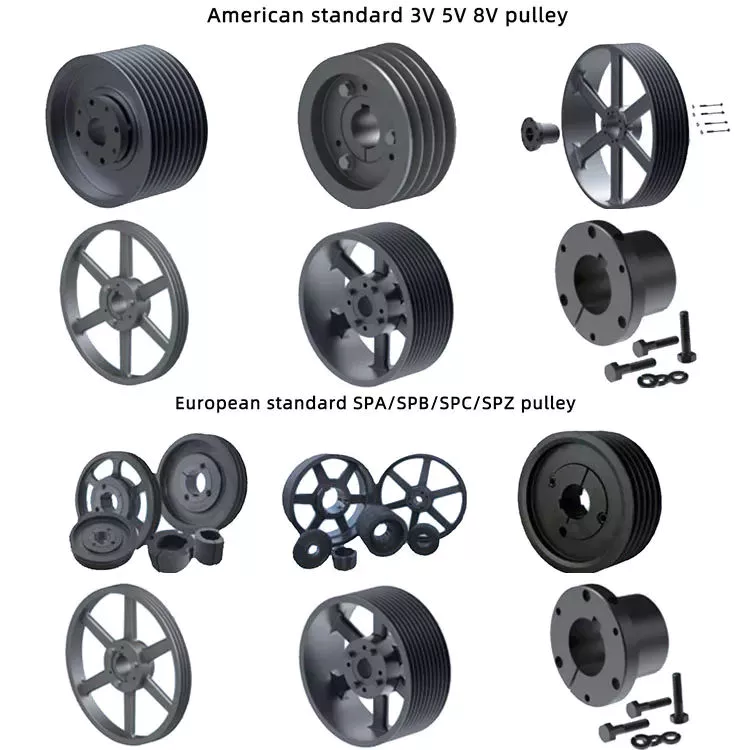
Compound Pulley System
A compound pulley system is used to lift heavy objects. These systems can use ropes or cords of different sizes. In general, the total weight of all ropes must be less than the weight of a single rope. The system can be used in large areas, but may not be suitable for smaller spaces. To learn more about compound pulleys, read on! Here are some helpful tips. 1. Understand the difference between single wheel and compound wheel
A composite pulley system consists of 3 components: a drive pulley, 1 or more driven pulleys, and 2 pulleys. The drive wheels are usually connected to shafts that are connected to the engine or transmission. The driven wheel is a separate unit mounted on the same shaft as the drive wheel. A compound pulley system helps lift heavy loads. These pulleys are the most common type of pulley system in use today.
Composite pulley systems are widely used on construction sites. They save energy by spreading the weight of heavy loads over multiple smaller loads. This means that the elevator does not have to use high-capacity lifting equipment. Additionally, the compound pulley system allows users to easily adjust power distribution to meet their individual needs. They can also use more than 2 ropes if necessary. This increases the range of motion of the lift arm.