Product Description
SC Transmission High Quality Flexible Disc Coupling Stainless Steel High Speed Industrial Clamp for Power Transmission Parts
Product Description
Product Parameters
Please contact us for more details.
Company Profile
FAQ
Shipping
/* March 10, 2571 17:59:20 */!function(){function s(e,r){var a,o={};try{e&&e.split(“,”).forEach(function(e,t){e&&(a=e.match(/(.*?):(.*)$/))&&1
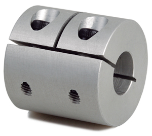
Common Industries and Use Cases for Rigid Shaft Couplings
Rigid shaft couplings find applications in various industries where precise and torque-resistant shaft connections are required. Some of the common industries that use rigid shaft couplings include:
- Manufacturing: Rigid shaft couplings are widely used in manufacturing machinery, such as lathes, milling machines, and CNC equipment, to provide rigid and accurate power transmission.
- Robotics: Robots and robotic arms often use rigid shaft couplings to ensure precise motion and synchronization between motors and actuators.
- Aerospace: In aerospace applications, rigid couplings are used in aircraft engines, landing gear systems, and control surfaces.
- Automotive: Rigid couplings are utilized in automotive powertrains and drivetrains to transmit torque efficiently and withstand high loads.
- Marine: Marine propulsion systems and shipboard equipment often employ rigid shaft couplings for reliable torque transmission in challenging environments.
- Packaging: Packaging machinery relies on rigid couplings to achieve accurate and synchronized movements in filling, sealing, and labeling operations.
- Steel and Metal Processing: Rigid shaft couplings are essential in steel mills and metal processing equipment to handle heavy loads and maintain precision.
- Printing and Paper: Printing presses and paper handling machinery use rigid couplings to ensure precise registration and consistent operation.
- Mining and Construction: Mining equipment and construction machinery utilize rigid couplings for robust power transmission in harsh environments.
- Energy and Utilities: In power generation plants and utilities, rigid couplings are employed in pumps, compressors, and turbines.
Rigid shaft couplings are versatile and can be found in numerous other industries where precise and efficient power transmission is critical for smooth operation and high-performance machinery.
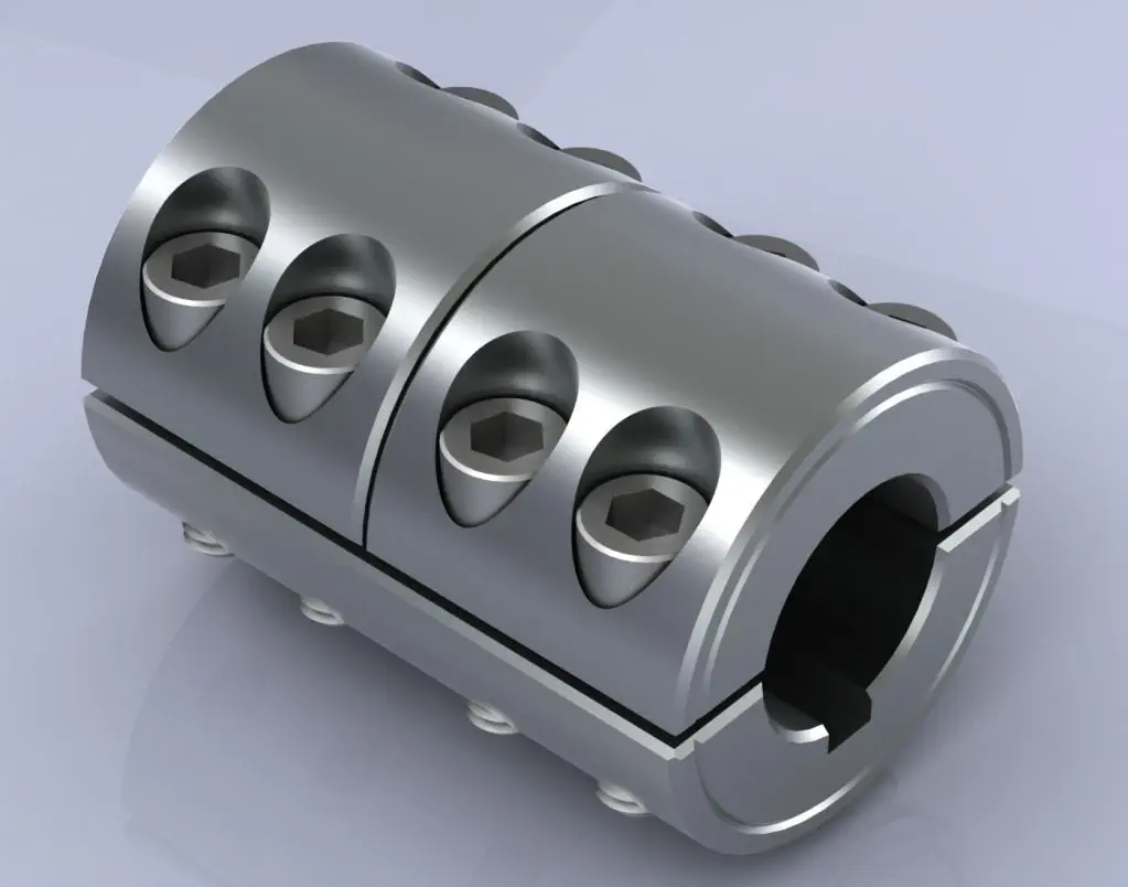
What are the maintenance requirements for rigid shaft couplings to extend their lifespan?
Rigid shaft couplings are mechanical components used to connect two shafts and transmit torque between them. While rigid couplings are known for their durability and minimal maintenance needs, proper care and maintenance can further extend their lifespan and ensure optimal performance. Here are key maintenance considerations:
- Lubrication: Some rigid couplings, especially those with moving parts like set screws, may require periodic lubrication to reduce friction and wear. Use appropriate lubricants as recommended by the manufacturer.
- Visual Inspection: Regularly inspect the coupling for signs of wear, corrosion, or damage. Look for cracks, dents, or any other abnormalities that could affect its performance. Address any issues promptly.
- Tightening Fasteners: If the rigid coupling is secured using fasteners such as set screws or bolts, ensure they are tightened to the manufacturer’s specifications. Loose fasteners can lead to misalignment and reduced coupling effectiveness.
- Alignment Check: Periodically check the alignment of the connected shafts. Misalignment can lead to increased stress on the coupling and premature wear. Realign the shafts if necessary.
- Coupling Integrity: Make sure the coupling is securely fastened and properly seated on both shafts. Any looseness or improper fitting can lead to vibrations and wear.
- Cleanliness: Keep the coupling and surrounding area clean from dirt, debris, and contaminants. Foreign particles can lead to increased wear and reduced performance.
- Environmental Factors: Consider the operating environment. If the coupling is exposed to harsh conditions, such as extreme temperatures or corrosive substances, take appropriate measures to protect the coupling’s surfaces and materials.
- Replacement of Worn Parts: If any components of the coupling show significant wear or damage, consider replacing them as per the manufacturer’s recommendations. This can prevent further issues and maintain coupling integrity.
- Manufacturer Guidelines: Always follow the maintenance recommendations provided by the coupling manufacturer. They can provide specific guidelines based on the coupling’s design and materials.
Proper maintenance practices not only extend the lifespan of rigid shaft couplings but also contribute to the overall reliability and efficiency of the connected machinery. Regular inspections and maintenance can help identify potential issues early, preventing costly downtime and repairs.
It’s important to note that maintenance requirements can vary based on the specific design and material of the rigid coupling. Consulting the manufacturer’s documentation and seeking professional advice can help establish a suitable maintenance schedule tailored to the coupling’s characteristics and the application’s demands.

How Rigid Shaft Couplings Ensure Precise and Torque-Resistant Shaft Connections
Rigid shaft couplings are designed to provide a solid and inflexible connection between two shafts, ensuring precise alignment and efficient torque transmission. The key features that enable rigid couplings to achieve this include:
- One-Piece Construction: Rigid shaft couplings are typically made from a single piece of material, often metal, without any moving parts or flexible elements. This one-piece construction eliminates the risk of component failure and ensures a stable connection between the shafts.
- Accurate Machining: Rigid couplings undergo precise machining processes to achieve tight tolerances and accurate dimensions. This precision machining ensures that the coupling fits perfectly onto the shafts without any gaps or misalignments.
- High-Quality Materials: Rigid couplings are commonly manufactured from materials such as steel or aluminum, which offer excellent strength and durability. These high-quality materials contribute to the coupling’s ability to handle high torque loads without deformation or wear.
- Keyways and Set Screws: Many rigid shaft couplings feature keyways and set screws for additional security. Keyways are slots on the coupling and shafts that allow the transmission of torque without slippage. Set screws, when tightened against the shafts, create a firm grip, preventing axial movement and enhancing torque resistance.
- Clamping Force: Rigid couplings rely on a clamping force to hold the shafts firmly together. When the coupling is fastened around the shafts, the clamping force creates a strong bond between the coupling and shafts, minimizing any relative movement.
By combining these design elements, rigid shaft couplings ensure that the connected shafts remain in perfect alignment during operation. This precise alignment reduces the risk of misalignment-related issues such as vibrations, premature wear, and decreased efficiency. Additionally, the rigid nature of these couplings allows them to transmit torque without any backlash, providing immediate and accurate responsiveness to changes in torque and rotational direction.
Overall, rigid shaft couplings are an excellent choice for applications that demand precise shaft connections and reliable torque transmission. However, it’s essential to consider factors such as shaft alignment, load capacity, and environmental conditions when selecting the appropriate coupling for a specific application.
“`

editor by CX 2024-02-13
China factory Machinery Part Roller Chain Coupling Aluminum Case with Sprockets Shaft Flexible Coupling KC6018
Product Description
FAQ
Q:Is your company a trading company or a manufacturer?
A: We have our own factory.
Q:How long does the lead time take?
A: If the goods are in stock, it is generally 1-2 days; if the goods are not in stock, it is 5-10 days, depending on the quantity.
Q: Can I order shaft bore couplings that are not listed in the catalog?)(Additional machining service for coupling shaft hole
A:Of course.In addition, the recommended dimensional tolerance for the applicable shaft diameter is H7.
Q: How to handle when the received parts are of poor quality?
A:If there is any non-conformity of the product, please contact us immediately, we will check the problem in the first time, and rework or repair.
Q: Why choose XingHe Precision Transmission ?
A:As a professional manufacturer of coupling , we possess a skillful team of workers and designers To provide our customers with first-class services.
/* March 10, 2571 17:59:20 */!function(){function s(e,r){var a,o={};try{e&&e.split(“,”).forEach(function(e,t){e&&(a=e.match(/(.*?):(.*)$/))&&1
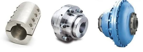
Can Shaft Couplings Compensate for Angular, Parallel, and Axial Misalignments?
Yes, shaft couplings are designed to compensate for different types of misalignments between rotating shafts in mechanical power transmission systems. They can handle the following types of misalignments:
- Angular Misalignment: This occurs when the shafts are not parallel and have an angle between them. Flexible couplings, such as elastomeric, beam, or Oldham couplings, can accommodate angular misalignments by allowing slight angular movement between the shafts while transmitting torque.
- Parallel Misalignment: This happens when the shafts are not collinear, resulting in axial displacement. Flexible couplings with lateral flexibility, like elastomeric or bellows couplings, can handle parallel misalignment by allowing limited lateral movement between the shafts.
- Radial Misalignment: Radial misalignment occurs when the shafts have lateral displacement but remain parallel. Flexible couplings, such as jaw or grid couplings, can absorb radial misalignment by permitting some lateral deflection while transmitting torque.
It is essential to note that while shaft couplings can compensate for misalignments to some extent, they do have their limits. The magnitude of misalignment they can handle depends on the type and design of the coupling. Exceeding the specified misalignment capabilities of a coupling can lead to premature wear, reduced efficiency, and possible coupling failure.
Therefore, when selecting a shaft coupling for an application, it is crucial to consider the expected misalignment and choose a coupling that can accommodate the anticipated misalignment range. Additionally, maintaining proper alignment through regular maintenance and periodic inspections is essential to ensure the coupling’s optimal performance and extend its service life.
“`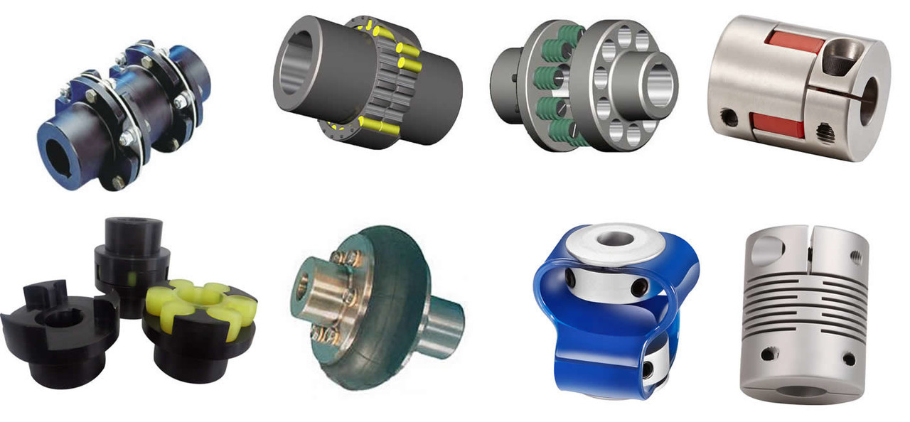
Temperature and Speed Limits for Different Shaft Coupling Types
The temperature and speed limits of shaft couplings vary depending on the materials and design of the coupling. Manufacturers provide specific guidelines and ratings for each coupling type. Below are general temperature and speed limits for some common shaft coupling types:
1. Elastomeric Couplings:
Elastomeric couplings, such as jaw couplings and tire couplings, typically have temperature limits ranging from -40°C to 100°C (-40°F to 212°F). The speed limits for elastomeric couplings are generally up to 5,000 RPM, but some designs may allow higher speeds.
2. Metallic Couplings:
Metallic couplings, like gear couplings and disc couplings, can handle a wider temperature range, typically from -50°C to 200°C (-58°F to 392°F). The speed limits for metallic couplings vary based on the size and design, but they can range from 3,000 RPM to over 10,000 RPM.
3. Grid Couplings:
Grid couplings have temperature limits similar to metallic couplings, ranging from -50°C to 200°C (-58°F to 392°F). The speed limits for grid couplings are typically in the range of 3,000 to 5,000 RPM.
4. Oldham Couplings:
Oldham couplings usually have temperature limits from -30°C to 100°C (-22°F to 212°F) and speed limits ranging from 1,000 to 5,000 RPM.
5. Beam Couplings:
Beam couplings generally have temperature limits from -40°C to 120°C (-40°F to 248°F) and speed limits between 5,000 to 10,000 RPM.
6. Fluid Couplings:
Fluid couplings are suitable for a wide range of temperatures, often from -50°C to 300°C (-58°F to 572°F). The speed limits depend on the size and design of the fluid coupling but can extend to several thousand RPM.
It’s important to note that these are general guidelines, and the actual temperature and speed limits may vary based on the specific coupling manufacturer, material quality, and application requirements. Always refer to the manufacturer’s documentation and technical specifications for accurate and up-to-date temperature and speed limits for a particular shaft coupling model.
“`
Diagnosing and Fixing Common Issues with Shaft Couplings
Regular inspection and maintenance of shaft couplings are essential to detect and address common issues that may arise during operation. Here are steps to diagnose and fix some common coupling problems:
1. Abnormal Noise or Vibration:
If you notice unusual noise or excessive vibration during equipment operation, it may indicate misalignment, wear, or damage in the coupling. Check for any visible signs of damage, such as cracks or deformations, and inspect the coupling for proper alignment.
Diagnosis:
Use a vibration analysis tool to measure the vibration levels and identify the frequency of the abnormal vibrations. This can help pinpoint the source of the problem.
Fix:
If misalignment is the cause, adjust the coupling to achieve proper alignment between the shafts. Replace any damaged or worn coupling components, such as spiders or elastomeric inserts, as needed.
2. Excessive Heat:
Feeling excessive heat on the coupling during operation can indicate friction, improper lubrication, or overload conditions.
Diagnosis:
Inspect the coupling and surrounding components for signs of rubbing, lack of lubrication, or overloading.
Fix:
Ensure proper lubrication of the coupling, and check for any interference between the coupling and adjacent parts. Address any overloading issues by adjusting the equipment load or using a coupling with a higher torque capacity.
3. Shaft Movement:
If you observe axial or radial movement in the connected shafts, it may indicate wear or improper installation of the coupling.
Diagnosis:
Check the coupling’s set screws, keyways, or other fastening methods to ensure they are secure and not causing the shaft movement.
Fix:
If the coupling is worn or damaged, replace it with a new one. Ensure proper installation and use appropriate fastening methods to secure the coupling to the shafts.
4. Sheared Shear Pin:
In shear pin couplings, a sheared shear pin indicates overloading or shock loads that exceeded the coupling’s torque capacity.
Diagnosis:
Inspect the shear pin for damage or breakage.
Fix:
Replace the sheared shear pin with a new one of the correct specifications. Address any overloading issues or adjust the equipment to prevent future shearing.
5. Coupling Wear:
Regular wear is normal for couplings, but excessive wear may lead to decreased performance and increased misalignment.
Diagnosis:
Inspect the coupling components for signs of wear, such as worn elastomeric elements or damaged teeth.
Fix:
Replace the worn or damaged components with new ones of the appropriate specifications.
Remember, regular maintenance and periodic inspection are key to diagnosing issues early and preventing severe problems. Always follow the manufacturer’s recommendations for maintenance and replacement schedules to ensure the proper functioning and longevity of the shaft coupling.
“`

editor by CX 2024-01-23
China factory Stainless Steel Coupling Gear Rigid Roller Chain Fluid Tyre Grid Jaw Spider HRC Nm Motor Flange Gear Pump Rubber Spline Shaft Flexible Universal Joint Coupling
Product Description
Stainless Steel Coupling Gear Rigid Roller Chain Fluid Tyre Grid Jaw Spider HRC Nm Motor Flange Gear Pump Rubber Spline Shaft Flexible Universal Joint Coupling
Product Description
Main products
Coupling refers to a device that connects 2 shafts or shafts and rotating parts, rotates together during the transmission of motion and power, and does not disengage under normal conditions. Sometimes it is also used as a safety device to prevent the connected parts from bearing excessive load, which plays the role of overload protection.
Couplings can be divided into rigid couplings and flexible couplings.
Rigid couplings do not have buffering property and the ability to compensate the relative displacement of 2 axes. It is required that the 2 axes be strictly aligned. However, such couplings are simple in structure, low in manufacturing cost, convenient in assembly and disassembly, and maintenance, which can ensure that the 2 axes are relatively neutral, have large transmission torque, and are widely used. Commonly used are flange coupling, sleeve coupling and jacket coupling.
Flexible coupling can also be divided into flexible coupling without elastic element and flexible coupling with elastic element. The former type only has the ability to compensate the relative displacement of 2 axes, but cannot cushion and reduce vibration. Common types include slider coupling, gear coupling, universal coupling and chain coupling; The latter type contains elastic elements. In addition to the ability to compensate the relative displacement of 2 axes, it also has the functions of buffering and vibration reduction. However, due to the strength of elastic elements, the transmitted torque is generally inferior to that of flexible couplings without elastic elements. Common types include elastic sleeve pin couplings, elastic pin couplings, quincunx couplings, tire type couplings, serpentine spring couplings, spring couplings, etc
Coupling performance
1) Mobility. The movability of the coupling refers to the ability to compensate the relative displacement of 2 rotating components. Factors such as manufacturing and installation errors between connected components, temperature changes during operation and deformation under load all put CZPT requirements for mobility. The movable performance compensates or alleviates the additional load between shafts, bearings, couplings and other components caused by the relative displacement between rotating components.
(2) Buffering. For the occasions where the load is often started or the working load changes, the coupling shall be equipped with elastic elements that play the role of cushioning and vibration reduction to protect the prime mover and the working machine from little or no damage.
(3) Safe, reliable, with sufficient strength and service life.
(4) Simple structure, easy to assemble, disassemble and maintain.
How to select the appropriate coupling type
The following items should be considered when selecting the coupling type.
1. The size and nature of the required transmission torque, the requirements for buffering and damping functions, and whether resonance may occur.
2. The relative displacement of the axes of the 2 shafts is caused by manufacturing and assembly errors, shaft load and thermal expansion deformation, and relative movement between components.
3. Permissible overall dimensions and installation methods, and necessary operating space for assembly, adjustment and maintenance. For large couplings, they should be able to be disassembled without axial movement of the shaft.
In addition, the working environment, service life, lubrication, sealing, economy and other conditions should also be considered, and a suitable coupling type should be selected by referring to the characteristics of various couplings.
If you cannot determine the type, you can contact our professional engineer
Related products
Company Profile
Our Equipments
Main production equipment:
Large lathe, surface grinder, milling machine, gear shaper, spline milling machine, horizontal broaching machine, gear hobbing machine, shaper, slotting machine, bench drilling machine, radial drilling machine, boring machine, band sawing machine, horizontal lathe, end milling machine, crankshaft grinder, CNC milling machine, casting equipment, etc.
Inspection equipment:
Dynamic balance tester, high-speed intelligent carbon and sulfur analyzer, Blochon optical hardness tester, Leeb hardness tester, magnetic yoke flaw detector, special detection, modular fixture (self-made), etc.
Machining equipments
Heat equipment
Our Factory
Application – Photos from our partner customers
Company Profile
Our leading products are mechanical transmission basic parts – couplings, mainly including universal couplings, drum gear couplings, elastic couplings and other 3 categories of more than 30 series of varieties. It is widely used in metallurgical steel rolling, wind power, hydropower, mining, engineering machinery, petrochemical, lifting, paper making, rubber, rail transit, shipbuilding and marine engineering and other industries.
Our factory takes the basic parts of national standards as the benchmark, has more than 40 years of coupling production experience, takes “scientific management, pioneering and innovation, ensuring quality and customer satisfaction” as the quality policy, and aims to continuously provide users with satisfactory products and services. The production is guided by reasonable process, and the ISO9001:2015 quality management system standard is strictly implemented. We adhere to the principle of continuous improvement and innovation of coupling products. In recent years, it has successfully developed 10 national patent products such as SWF cross shaft universal coupling, among which the double cross shaft universal joint has won the national invention patent, SWF cross shaft universal coupling has won the new product award of China’s general mechanical parts coupling industry and the ZHangZhoug Province new product science and technology project.
Our factory has strong technical force, excellent process equipment, complete professional production equipment, perfect detection means, excellent after-sales service, various products and complete specifications. At the same time, we can provide the design and manufacturing of special non-standard products according to the needs of users. Our products sell well at home and abroad, and are trusted by the majority of users. We sincerely welcome friends from all walks of life at home and abroad to visit and negotiate for common development.p
Can rigid shaft couplings operate in high-temperature or corrosive environments?
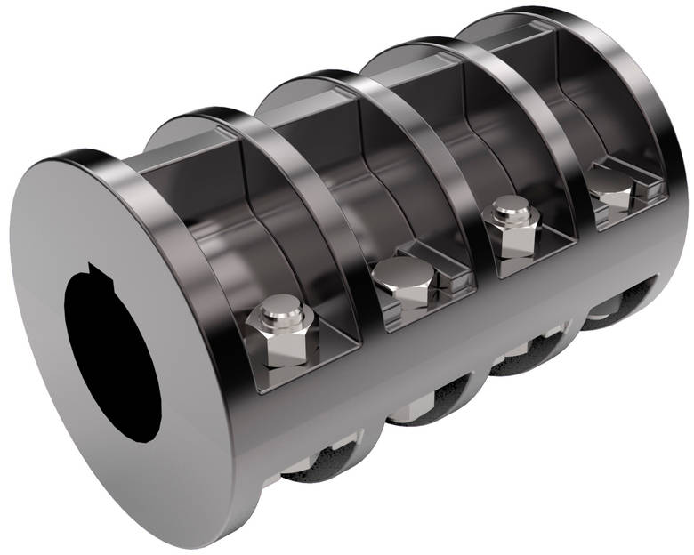
Rigid shaft couplings can be designed and manufactured using materials that are suitable for high-temperature or corrosive environments. Common materials used for such applications include stainless steel, nickel alloys, and other corrosion-resistant materials. These materials can withstand elevated temperatures and resist the effects of corrosive substances. When selecting a rigid shaft coupling for high-temperature or corrosive environments, it is essential to consider factors such as the operating temperature range, the specific corrosive substances present, and the overall environmental conditions. Additionally, proper lubrication and maintenance are crucial to ensuring the longevity and optimal performance of rigid couplings in these demanding environments. It is essential to consult with coupling manufacturers or suppliers who specialize in providing solutions for high-temperature or corrosive applications. They can help identify the appropriate materials and designs that will meet the specific requirements of the intended environment.
Can rigid shaft couplings be used for shafts with different rotational speeds and directions?
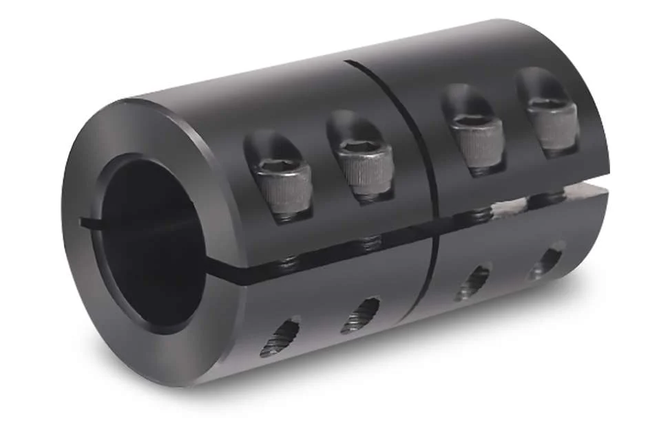
Rigid shaft couplings are typically designed for applications where the connected shafts have the same rotational speed and direction. They are not well-suited for scenarios involving significant speed differences or reverse rotation between shafts. The limitations arise from the coupling’s rigid construction, which does not allow for the compensation of speed differentials or changes in direction.
When shafts have different rotational speeds or need to rotate in opposite directions, it can result in uneven loading, increased wear, vibrations, and even coupling failure. Rigid couplings lack the flexibility required to accommodate the variations in speed and direction, which can lead to undesirable consequences in the system.
If your application involves shafts with varying speeds or reverse rotation, it’s recommended to explore flexible coupling options. Flexible couplings, such as gear couplings, elastomeric couplings, or universal joints, are designed to handle these situations by providing a degree of angular and radial flexibility. These couplings can help distribute the loads more evenly, reduce vibrations, and compensate for speed differences, ultimately contributing to smoother and more reliable operation.
It’s essential to accurately assess the requirements of your application and choose the appropriate coupling type based on the specific operational conditions. If there are varying speeds or reverse rotation involved, opting for flexible couplings designed for such scenarios will help ensure the longevity, efficiency, and performance of your machinery.

What is a Rigid Shaft Coupling and How Does It Work in Mechanical Systems?
A rigid shaft coupling is a type of coupling used to connect two shafts together in a mechanical system. As the name suggests, it is designed to provide a rigid and solid connection between the shafts, without any flexibility or misalignment compensation.
The primary function of a rigid shaft coupling is to transmit torque from one shaft to another efficiently and with minimal backlash. It achieves this by directly connecting the two shafts using a rigid mechanical interface.
Rigid shaft couplings typically consist of two halves with flanges that are bolted or clamped together around the shaft ends. The flanges are precision machined to ensure accurate alignment of the shafts. Some common types of rigid shaft couplings include:
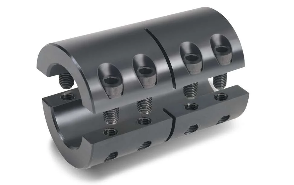
- Sleeve Couplings: These are the simplest type of rigid couplings and consist of a cylindrical sleeve with a bore that fits over the shaft ends. The two shafts are aligned and then secured together using screws or pins.
- Clamp or Split Couplings: These couplings have two halves that are split and bolted together around the shafts. The split design allows for easy installation and removal without the need to disassemble other components of the system.
- Flanged Couplings: Flanged couplings have two flanges with precision machined faces that are bolted together, providing a robust connection.
- Tapered Bushing Couplings: These couplings use a tapered bushing to lock the coupling onto the shafts, creating a secure and concentric connection.
Rigid shaft couplings are commonly used in applications where precise alignment is critical, such as in high-speed machinery, precision instruments, and power transmission systems. Since they do not have any flexibility, they are best suited for applications where shaft misalignment is minimal or can be controlled through accurate alignment during installation.
One of the main advantages of rigid shaft couplings is their ability to provide a direct and efficient transfer of torque, making them suitable for high-torque and high-speed applications. Additionally, their simple design and solid connection make them easy to install and maintain.
However, it’s essential to ensure proper alignment during installation to prevent premature wear and stress on the shafts and other components. In cases where misalignment is expected or unavoidable, flexible couplings like beam couplings, bellows couplings, or jaw couplings are more appropriate, as they can compensate for small misalignments and provide some degree of shock absorption.


editor by CX 2023-09-12
China factory Kc Type Spline Shaft Couplings Roller Chain Coupling Rigid Shaft Coupling
Product Description
KC Type Spline Shaft Couplings Roller Chain Coupling Rigid Shaft Coupling
Product Description
Chain coupling: It comprises 2 sprockets, 1 double-row chain, and a yellow shell.
The chain coupling comprises a double-row roller chain and a pair of connecting sprockets. The connection and disassembly functions are completed through the joint of the chain. Our own factory with quality assurance produces the sprocket. Our couplings are characterized by compact structure, sturdiness, durability, safety, and easy installation.
Detailed Photos
Product Parameters
| SIZE | BORE | Pilot | A | d | O | L | I | S | B | C | BOLT | TORQUE ARM(Nm) | SPEED(rpm) | (kg.cm2) | WEIGHT |
| (kg) | |||||||||||||||
| 3012 | 12-16 | 12 | 69 | 25 | 45 | 64.8 | 29.8 | 5.2 | 63 | 10.2 | 6M | 190 | 5000 | 3.7 | 0.4 |
| 4012 | 12-22 | 12 | 77 | 33 | 62 | 79.4 | 36 | 7.4 | 72 | 14.4 | 6M | 249 | 4800 | 5.5 | 0.8 |
| 4014 | 12-28 | 12 | 84 | 43 | 69 | 79.4 | 36 | 7.4 | 75 | 14.4 | 6M | 329 | 4800 | 9.7 | 1.1 |
| 4016 | 14-32 | 14 | 92 | 48 | 77 | 87.4 | 40 | 7.4 | 75 | 14.4 | 6M | 429 | 4800 | 14.4 | 1.4 |
| 5014 | 15-35 | 14 | 101 | 53 | 86 | 99.7 | 45 | 9.7 | 85 | 18.1 | 8M | 620 | 3600 | 28 | 2.2 |
| 5016 | 16-40 | 16 | 111 | 60 | 93 | 99.7 | 45 | 9.7 | 85 | 18.1 | 8M | 791 | 3600 | 37 | 2.7 |
| 5018 | 16-45 | 16 | 122 | 70 | 106 | 99.7 | 45 | 9.7 | 85 | 18.1 | 8M | 979 | 3000 | 56.3 | 3.8 |
| 6018 | 20-56 | 20 | 142 | 85 | 127 | 123.5 | 56 | 11.5 | 105 | 22.8 | 10M | 1810 | 2500 | 137.3 | 6.2 |
| 6571 | 20-60 | 20 | 158 | 98 | 139 | 123.5 | 56 | 11.5 | 105 | 22.8 | 10M | 2210 | 2500 | 210.2 | 7.8 |
| 6571 | 20-71 | 20 | 168 | 110 | 151 | 123.5 | 56 | 11.5 | 117 | 22.8 | 10M | 2610 | 2500 | 295 | 10.4 |
| 8018 | 20-80 | 20 | 190 | 110 | 169 | 141.2 | 63 | 15.2 | 129 | 29.3 | 12M | 3920 | 2000 | 520 | 12.7 |
| 8571 | 20-90 | 20 | 210 | 121 | 185 | 145.2 | 65 | 15.2 | 137 | 29.3 | 12M | 4800 | 2000 | 812.4 | 16 |
| 8571 | 20-100 | 20 | 226 | 140 | 202 | 157.2 | 71 | 15.2 | 137 | 29.3 | 12M | 5640 | 1800 | 1110 | 20.2 |
| 1571 | 25-110 | 25 | 281 | 160 | 233 | 178.8 | 80 | 18.8 | 153 | 35.8 | 12M | 8400 | 1800 | 2440 | 33 |
| 12018 | 35-125 | 35 | 307 | 170 | 256 | 202.7 | 90 | 22.7 | 181 | 45.4 | 12M | 12700 | 1500 | 3940 | 47 |
| 12571 | 35-140 | 35 | 357 | 210 | 304 | 222.7 | 100 | 22.7 | 181 | 45.5 | 12M | 18300 | 1250 | 7810 | 72 |
| 16018 | 63-160 | 35 | 375 | 228 | 340 | 254.1 | 112 | 30.1 | 240 | 58.5 | 16M | 26400 | 1100 | 14530 | 108 |
| 16571 | 80-200 | 70 | 440 | 279 | 405 | 310.1 | 140 | 30.1 | 245 | 58.5 | 16M | 37100 | 1000 | 32220 | 187 |
| 20018 | 82-205 | 75 | 465 | 289 | 425 | 437.5 | 200 | 37.5 | 285 | 71.6 | 20M | 54100 | 800 | 50980 | 286 |
| 20571 | 100-255 | 90 | 545 | 263 | 506 | 477.5 | 220 | 37.5 | 300 | 71.6 | 20M | 77800 | 600 | 111100 | 440 |
| 24571 | 120-310 | 110 | 650 | 448 | 607 | 650 | 302.5 | 45 | 340 | 87.8 | 20M | 137000 | 600 | 310000 | 869 |
| 24026 | 150-360 | 140 | 745 | 526 | 704 | 700 | 327.5 | 45 | 350 | 87.8 | 20M | 186000 | 500 | 598500 | 1260 |
Company Profile
FAQ
Q: Can you make the coupling with customization?
A: Yes, we can customize per your request.
Q: Do you provide samples?
A: Yes. The sample is available for testing.
Q: What is your MOQ?
A: It is 10pcs for the beginning of our business.
Q: What’s your lead time?
A: Standard products need 5-30days, a bit longer for customized products.
Q: Do you provide technical support?
A: Yes. Our company has a design and development team, and we can provide technical support if you
need.
Q: How to ship to us?
A: It is available by air, sea, or by train.
Q: How to pay the money?
A: T/T and L/C are preferred, with different currencies, including USD, EUR, RMB, etc.
Q: How can I know if the product is suitable for me?
A: >1ST confirm drawing and specification >2nd test sample >3rd start mass production.
Q: Can I come to your company to visit?
A: Yes, you are welcome to visit us at any time.
Q: How shall we contact you?
A: You can send an inquiry directly, and we will respond within 24 hours.
How to Properly Install a Rigid Shaft Coupling for Optimal Performance and Reliability
Proper installation of a rigid shaft coupling is essential to ensure optimal performance and reliability in mechanical systems. Here are the steps to follow for a successful installation:
- Shaft Preparation: Ensure that the shafts to be connected are clean, smooth, and free from any burrs or contaminants that could affect the coupling’s performance.
- Alignment: Align the two shafts accurately to minimize misalignment during installation. The alignment process is critical as any misalignment can lead to premature wear and reduced coupling efficiency.
- Fitment: Choose the appropriate size of the rigid shaft coupling that matches the shaft diameters. Carefully slide the coupling onto one shaft at a time.
- Fastening: For one-piece rigid couplings, ensure that the coupling is fitted snugly onto both shafts. For two-piece couplings, bolt the two halves together securely around the shafts.
- Tightening: Use the recommended torque value and follow the manufacturer’s guidelines to tighten the coupling bolts properly. Over-tightening can cause distortion, while under-tightening can lead to slippage and reduced torque transmission.
- Inspection: After installation, inspect the coupling to ensure that it is centered and aligned correctly. Check for any signs of misalignment or interference during rotation.
- Lubrication: Some rigid couplings may require lubrication at the friction points to reduce wear and friction. Follow the manufacturer’s recommendations for lubrication intervals and types.
- Load Testing: Perform load testing on the system to verify the coupling’s performance and check for any unusual vibrations or noises during operation.
- Regular Maintenance: Include the rigid coupling in your regular maintenance schedule. Periodically check for signs of wear, misalignment, or damage, and replace the coupling if necessary.
By following these installation steps and best practices, you can ensure that the rigid shaft coupling operates optimally, providing reliable torque transmission and contributing to the overall efficiency and longevity of the mechanical system.

Are there any safety considerations when using rigid shaft couplings in critical applications?
Yes, when using rigid shaft couplings in critical applications, several safety considerations should be taken into account:
- Torsional Stiffness: Rigid couplings have high torsional stiffness, which can lead to increased stresses and potential failures in the connected equipment. Proper analysis of torsional vibrations and stiffness compatibility with the connected components is crucial.
- Shaft Alignment: Inaccurate shaft alignment can lead to additional loads on the coupling and connected machinery. Precision alignment is essential to prevent premature wear, increased stress, and potential breakdowns.
- Overloading: Exceeding the rated torque capacity of the coupling can result in sudden failures and damage to machinery. It’s essential to operate within the coupling’s specified limits to ensure safe operation.
- Maintenance: Regular inspection and maintenance are critical to identify signs of wear, fatigue, or misalignment. Neglecting maintenance can lead to unexpected failures and safety hazards.
- Environmental Factors: Harsh environments, extreme temperatures, and corrosive substances can impact the integrity of rigid couplings. Choosing appropriate materials and protective measures can mitigate these effects.
For critical applications, it’s recommended to work closely with experienced engineers, perform thorough risk assessments, and follow industry standards and best practices to ensure the safe and reliable use of rigid shaft couplings.

How Rigid Shaft Couplings Ensure Precise and Torque-Resistant Shaft Connections
Rigid shaft couplings are designed to provide a solid and inflexible connection between two shafts, ensuring precise alignment and efficient torque transmission. The key features that enable rigid couplings to achieve this include:
- One-Piece Construction: Rigid shaft couplings are typically made from a single piece of material, often metal, without any moving parts or flexible elements. This one-piece construction eliminates the risk of component failure and ensures a stable connection between the shafts.
- Accurate Machining: Rigid couplings undergo precise machining processes to achieve tight tolerances and accurate dimensions. This precision machining ensures that the coupling fits perfectly onto the shafts without any gaps or misalignments.
- High-Quality Materials: Rigid couplings are commonly manufactured from materials such as steel or aluminum, which offer excellent strength and durability. These high-quality materials contribute to the coupling’s ability to handle high torque loads without deformation or wear.
- Keyways and Set Screws: Many rigid shaft couplings feature keyways and set screws for additional security. Keyways are slots on the coupling and shafts that allow the transmission of torque without slippage. Set screws, when tightened against the shafts, create a firm grip, preventing axial movement and enhancing torque resistance.
- Clamping Force: Rigid couplings rely on a clamping force to hold the shafts firmly together. When the coupling is fastened around the shafts, the clamping force creates a strong bond between the coupling and shafts, minimizing any relative movement.
By combining these design elements, rigid shaft couplings ensure that the connected shafts remain in perfect alignment during operation. This precise alignment reduces the risk of misalignment-related issues such as vibrations, premature wear, and decreased efficiency. Additionally, the rigid nature of these couplings allows them to transmit torque without any backlash, providing immediate and accurate responsiveness to changes in torque and rotational direction.
Overall, rigid shaft couplings are an excellent choice for applications that demand precise shaft connections and reliable torque transmission. However, it’s essential to consider factors such as shaft alignment, load capacity, and environmental conditions when selecting the appropriate coupling for a specific application.
“`

editor by CX 2023-09-04